Monday, April 27, 2015

P2 - ESP8266 Ultimate DevBoard - Firmware upload and first run


  Part 2 of the the new CBDBv2 Evolution Series


  Let's begin our today story with a quick remember of the CBDBv2 DevBoard features:


    Finished Board with headers and some EXT modules in place:

CBDB Evolution - bottom view

EXT Modules


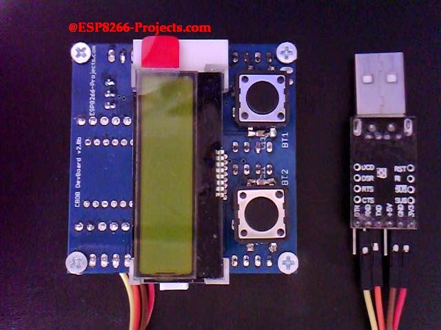
CBDB Evolution - top view

   First thing to see is how easy is the process to configure and start using CBCBv2 (code name Evolution) Board. It will come preconfigured with NodeMCU, so, if LUA is your desired programming language you can just start using it.

   In case of firmware update needed or if you want to change the environment, it is a very easy process, similar with the one used for MPSM Board.


   What we will need:


Uploading  new firmware:


1. Using the clasic "jumper-style" procedure

  • connect CBDB Module with the USB Adapter (Tx, Rx, 3v3, GND), Set the PROG jumper in the Programming mode position (closed) and power on

CBDBv2 - Firmware Programming mode enabled

  • Start NodeMCU Flasher. Choose you USB adapter corresponding port
  • Add from Config Menu latest previously downloaded firmware. It must start from 0x0000. Disable anything else. 
  • Go back on Operation tab. Power off your CBDB Module. Press FLASH Button. power ON quick CBDB module. It will be recognised and will start flashing. Give it a second try if necessary.
  •  When finished succesfully A green OK checkmark will appear
  •  Power Off CBDB Module, Remove yellow jumper. Power back ON. Your CBDBv2 Board should be now programmed with the new NodeMCU Firmware.


    If you change very often the firmware or want a easier way to use CBDBv2 DevBoard with Arduino IDE or direct GCC/Eclipse programming then maybe you will prefer the second available procedure for uploading your firmware:


2. Using the Auto reset/bootloading mode:

   Another great tool for uploading new firmware for your CBDBv2 DevBoard is esptool.
I want to thank you themadinventor for such a great utility program and also want to thank for the received improvements from several members of the ESP8266 community, including pfalcon, tommie, 0ff and george-hopkins. Great job!

   We will use in this example the CK version (thank you Christian) but any version of esptool that is supporting the RTS/DTR reset/bootloading mode must work ok. If you want to avoid compiling yourself the program you can download the binary file from here:  esptool-bin.zip


    Upload procedure:
  • connect CBDB Module with the USB Adapter (Tx, Rx, RTS, DTR, 3v3, GND) and power on
Auto reset/bootloading mode configuration


  • In Command Prompt Start esptool.exe program:
         D:\ESPTool>esptool.exe -cp COM34 -cd ck -cf nodemcu_latest.bin

          cp  - Select the serial port device to use for communicating with the ESP.
          cd  - Select the reset method to use for resetting the board.
          cf  - Select the firmware file that you want to flash memory


   For further programming in LUA, it might be possible to do it directly in your Serial Terminal Program but I will recomend you to use a more dedicated program for that, like LuaLoader or LuaUploader. I will stay with the latest one, for it's great flexibility and simplicity.

   To run a quick test, you can just use the code snippets provided by LuaUploader at start-up. Select the piece of code that you want to run and press "Execute Selection" button.

  • To quick setup your WIFI network :
        -- One time ESP Setup --
        wifi.setmode(wifi.STATION)
         wifi.sta.config ( "YOUR_WIFI_SSID" , "PASSWORD" ) 
         print(wifi.sta.getip())


  • For the Blinky test, just use a prepared LED as in the picture, insert it on previously used yellow jumper place (GPIO0) and run the code from below
Be careful with Anode / catode orientation

                -- Blink using timer alarm --
                timerId = 0 -- we have seven timers! 0..6
                dly = 500 -- milliseconds
                ledPin = 3 -- 3=GPIO0
                gpio.mode(ledPin,gpio.OUTPUT)
               ledState = 0
               tmr.alarm( timerId, dly, 1, function()
                  ledState = 1 - ledState;
                  gpio.write(ledPin, ledState)
               end)


UPDATE !! UPDATE !! UPDATE !!


Yes, it's true.

For all the Arduino IDE lovers:

Arduino IDE first test for direct programming and firmware uploading on the new ESP8266 CBDBv2 Evolution DevBoard. No manual reset needed , no buttons to press, just press Upload and that's it!

 Running Blinky LED program on GPIO15:

// the setup function runs once when you press reset or power the board
void setup() {
     // initialize digital pin 15 as an output.
     pinMode(15, OUTPUT);
}

// the loop function runs over and over again forever
void loop() {
     digitalWrite(15, HIGH);   // turn the LED on (HIGH is the voltage level)
     delay(500);              // wait for a second
     digitalWrite(15, LOW);    // turn the LED off by making the voltage LOW
     delay(500);              // wait for a second
}


Friday, April 24, 2015

ESP8266 Ultimate DevBoard - Finally Arrived!!


   What do you really expect from a IOT Development board?

   I'm sure most of you will say easy configurable Internet access. Direct Wifi if possible.

   And after that?

   What do you think do you need mostly for your IOT Projects?

   Maybe some sort of easy interaction and data exchange with the real world environment?


  Sounds intriguing to start with so many questions but they are more than legitimate:

  When removing all the bells and whistles, what do we REALLY need to develop the next level of IOT devices?


    If you asked yourself already all these questions, and I'm sure a lot of you has done it already, thinking on your own future projects, what do you think about a IOT Development Board that can offer you at least:


   Sounds good? sounds impossible? Well...I hope that I have, at least for a part of you, one of the right answers below:

CBDB v2 Schematic


  A DevBoard full of functions in a 5x5 size PCB, small enough to easy integrate in your hobbyist workplace ecosystem :)


CBDB V2 DevBoard PCB - TOP


   Latest design review PCBs of the fresh new ESP8266 Dev Board v.2 just landed on my desk and is definitely a next step in Experimenting in the IOT world. Designed with ease of use and flexibility in mind it will offer you endless hours of Experimenting, Programming and Developing your own projects.


     For any new requests please feel free to use as usual: tech at esp8266-projects.com.
     If you want for your own experiments to order CBD v2 EVO bare PCBs only, you can also do it directly at Dirty PCBs, our preferred PCB House:
  http://dirtypcbs.com/view.php?share=5876&accesskey=3d0fd70d53d6dc20c0bf0255f67cde65

     Please keep in mind this is a experimental board, not a commercial product and is offered as it is. If it will burn your house, help the Aliens to abduct you or even eat your cat it's your problem not mine. The old enough ones to remember ALF will understand even deeper the disclaimer :)


  On the TOP side, you can easily directly integrate your LCD or if you want it separate just run it thru a usual cable:
 
CBDB v2 - TOP


     After finished soldering, cleaning and cooling down, this is how is looking the ESP8266 CBDBv2 DevBoard ready for testing  the onboard regulator :


Testing was done with power supplied from a Li-Ion Battery pack and also from a standard 5V SMPS unit under a decent 500mA load. No overheating or nasty oscillations, looks good up to 800mA. Are 800mA warm but the proper calculated double side heatsink area is doing the job right :).


Onboard regulator test - 5V  SMPS Supply


    I know it's a big debate this days about 1A requirement for ESP8266 Modules, but from all my experience and informations, at least with the ESP-07/12 Modules I had in my hands in the latest months, they were never exceed the 250mA margin. In fact, I have one module running for months now as a temperature logger/webserver and the power consumption looks constantly as in the pictures below:

Full drain test with thinkspeak data upload and 1/s direct web access reload


Temperature  Logger supply line monitoring


   I must also admit that I have also some old ESP-01 Modules, never used them, they are indeed looking very power hungry but never had the time to check them how much power they require to properly operate. Or if they are just faulty.

   I have seen before entire batches of faulty ESP8266 modules. Even ESP-07 ones if you remember the story. What I can confirm about these ESP-01 modules is that they cannot be programmed using power directly from my CP2102 USB Adapter, as ESP-07/12. Not enough juice for them. Why? If I will find some time will take a look at them. If is anybody out there that has the answer, please share it with us.


And finally, this is how is looking, ready for firmware upload and first tests:
 ESP8266 DevBoard

Stay tuned for what will follow soon:  firmware uploading and the infamous Blinky test:)


Friday, April 17, 2015

P2 - WIFI Web Power Switch for MAINS - MPSM v.2 DevBoard - ESP8266


UPDATE!! UPDATE !!

New released MPDMv4 (MAINS Power Dimmer) Driver Board !


--------------------------------------------------------------------------------------------------------------------------

WARNING!! You will play with LIVE MAINS!! Deadly zone!! 


If you don't have any experience and are not qualified for working with MAINS power I will not ecourage you to play arround!

---------------------------------------------------------------------------------------------------------------------------- 

    Remember the story about the WIFI MAINS Power Switch module

    Because of the high interest in the subject, a new dedicated Dev Board has been born MPSMv2, a small ESP8266 DevBoard with integrated MAINS Power Switch! 

   Yes, it's finally here, arrived safely from the PCB factory and you can see it below. I know a lot of you are waiting it already, but please be patient few more days. None of the already requested ones will leave the premises without a proper 24 hour test.
  
   For any new requests please feel free to use as usual: tech at esp8266-projects.com.
     If you want for your own experiments to order CBD v2 EVO bare PCBs only, you can also do it directly at Dirty PCBs, our preferred PCB House:


MPSM v2 Schematic


    Theory of operation remain the same so please take a look at the previous Article about MAINS Power Switch for deeper explanations.

     I don't know if this it's the smallest MAINS Power Switch with integrated WIFI and direct Web interface access but if is not, it's definitely closer to be at only around 25x50mm :)

MPSM v2 - PCB - TOP
    As you can see from the PCB picture above you have even a full ESP8266 pinout access thru 2 breadboard friendly expansion slots for future projects development.


   Finally,  the received result from the PCB Factory, a long awaited moment:

MPSM v2  PCB Batch


MPSM v2 - TOP


      If you want to have a separate Breadboard friendly ESP8266 adapter with integrated 3.3V Power Supply, you can cut the board in 2 independent working parts, the ESP07/12 adapter and the MAINS Triac Switch.

    It is designed in such way that no harm will be done by the cut to the functioning of the circuit. You can use the cut MAINS Power Switch part directly even with your ARM, PIC, Arduino, whatever MCU you like this days without any problems as long as it has a GPIO pin capable to drive the MOC Optocoupler LED.

MPSM v2  - separate usage ESP8266 adapter and MAINS Switch

ESP8266 ESP-07/12 Adapter


      And the final result, a fresh baked one, ready for testing:

MPSM v2 - full asembled


MPSM v2 - full asembled - bottom


-----------------------------------------------------------------------------------------------------------------
   Before going further and start running some tests few considerations to be done:
  • Do NOT use it without proper Knowledge about MAINS circuits !
  • Do NOT use it without a proper FUSE on MAINS line! 
  • This is NOT a Toy!
-----------------------------------------------------------------------------------------------------------------


     What we will need:
  • MPSM DevBoard from above
  • USB adapter (take a look on Part 1 for details how to connect them together)  
  • NodeMCU firmware (download latest - can use the floating point version for now) 
  • NodeMCU Flasher ( firmware programmer for NodeMCU DEVKIT) 
  • For programming MPSM v2 DevBoard and uploading the software we will continue to use the LuaUploader as before. 


    Flashing the MPSM NodeMCU Firmware is a straigth away process:
  
Programming MPSM v2 Board


  •  Connect MPSM Board with the USB Adapter, Set the PROG jumper (YELLOW) in the  Programming mode position (closed) and power on 
  • Start NodeMCU Flasher. Choose you USB adapter corresponding port
  • Add from Config Menu latest previously downloaded firmware. It must start from 0x0000. Disable anything else. 
  • Go back on Operation tab. Power off your MPSM Board. Press FLASH Button. power ON quick MPSM Board. It will be recognised and will start flashing. Give it a second try if necessary.
  • When finished succesfully A green OK checkmark will appear
  • Power Off   MPSM Board, Remove yellow jumper. Power back ON. A NodeMCU programmed MPSM Board is ready for action :)


    For a more detailed explanation for NodeMCU Firmware flashing please take a look at CBDB Board Firmware Flashing discussion


 To quick run a test we will use the code snippets provided by LuaUploader at start-up. Select the piece of code that you want to run and press "Execute Selection" button.


  • To quick setup your WIFI network - If this is your first project with a new ESP module that was never used in your WIFI Network, don't forget it - one time only :
            -- One time ESP Setup --
            wifi.setmode(wifi.STATION)
            wifi.sta.config ( "YOUR_WIFI_SSID" , "PASSWORD" ) 
            print(wifi.sta.getip())


  • For the Triac Optocoupler Command testing we will use the "Blinky" part of the code and if all ok it will blink LED2 with the choosen rate "dly".
          Run the modified code from below:

          -- Blink using timer alarm --
          timerId = 0 -- we have seven timers! 0..6
          dly = 500 -- milliseconds
          ledPin = 1 -- 1=GPIO5  - allocated pin for Triac opto command
          gpio.mode(ledPin,gpio.OUTPUT)
          ledState = 0
          tmr.alarm( timerId, dly, 1, function()
                ledState = 1 - ledState;
                 gpio.write(ledPin, ledState)
          end)


  Now you can connect you MAINS powered lightbulb and you can see it playing the "Blinky" game too :).  Use proper heatsink for power disipation for your Triac.


    Power Switch function and WEB Server software are the same as in previous article about CBDB WIFI MAINS power switch  just change the used GPIO Triac opto command pin from outpin=3 to outpin=1 to properly reflect our new MPSM v2 Board setup


For a MAINS Power Dimmer Module, take a look at the new MPDMv3 Module


UPDATE !! UPDATE !! UPDATE !!

As many of you asked for a BOM list, please find it below:

Part Value Device
Package Description


R1 560 R-EU_R1206
R1206 RESISTOR, European symbol
R2 10k R-EU_R1206
R1206 RESISTOR, European symbol
R3 10k R-EU_R1206
R1206 RESISTOR, European symbol
R4 10k R-EU_R1206
R1206 RESISTOR, European symbol
R5 10k R-EU_R1206
R1206 RESISTOR, European symbol
R6 470 R-EU_R1206
R1206 RESISTOR, European symbol
R7 470 R-EU_0207/10
0207/10 RESISTOR, European symbol
R8 390 R-EU_0204/7
0204/7 RESISTOR, European symbol
R9 470 R-EU_R1206
R1206 RESISTOR, European symbol
R10 39/1W R-EU_0309/10
0309/10 RESISTOR, European symbol


C1 100n C-EUC1210
C1210 CAPACITOR, European symbol
C2 100u C-EUC1210
C1210 CAPACITOR, European symbol
C3 0.1u/400V C-EU075-032X103
C075-032X103 CAPACITOR, European symbol


IC1 REG1117 REG1117
SOT223 1A LDO Positive Regulator


LED1
LEDCHIPLED_1206
CHIPLED_1206 LED
LED2
LED3MM
LED3MM LED


OK1 MOC3041M MOC3041M
DIL06 6-Pin DIP ZCD Optoisolator Triac Driver
T1 BT137 BT137-600
TO220BV TRIAC - BT137/600 - NXP


AC_MAINS
MTA02-156
1X2MTA AMP connector
CMD
PINHD-1X2
1X02 PIN HEADER
JP1
PINHD-1X8BIG
1X08-BIG PIN HEADER
JP2
PINHD-1X8BIG
1X08-BIG PIN HEADER
PRG
PINHD-1X2
1X02 PIN HEADER
VIN
PINHD-1X2
1X02 PIN HEADER


ESP12 ESP-12 ESP8266_ESP-12
ESP8266-ESP12


Tuesday, April 14, 2015

AT24C32 - I2C External EEPROM Data Looger


      As you remember from our previous article about DS3231 RTC Module, we have identified onboard an EEPROM chip, a 32k AT24C32 one. It is independent from the RTC circuit and conected on the I2C bus, perfect companion for a Data Logger System :)


AT24C32 EEPROM


     The AT24C32 provides 32,768 bits of serial electrically erasable and programmable read only memory (EEPROM) organized as 4096 words of 8 bits each. Might not sound too much but believe it or not you can log 6 months of data or even more on it depending on your application requests and how you organize your data logging

    For example if you save your data in 1byte, you will have enough for around 170 days or 24 weeks! With an added 16 extra location available for bulding data header/date/time/CRC/whatever your needs ask for. And if you still feel it to small, you can use anytime AT24C64, 64k size (8192 x 8), direct drop-in replacement!

     Also the device’s cascadable feature allows up to 8 devices to share a common I2C bus. The device is optimized for use in many industrial and commercial applications where low power and low voltage operation are essential. In addition, the entire family is available in 2.7V (2.7V to 5.5V) and 1.8V (1.8V to 5.5V)versions.


     FEATURES:

     • Low-Voltage and Standard-Voltage Operation
          –  2.7 (VCC = 2.7V to 5.5V)
          –  1.8 (VCC = 1.8V to 5.5V)
     • Low-Power Devices (ISB = 2μA at 5.5V) Available
      • Internally Organized 4096 x 8
      • 2-Wire Serial Interface
      • Schmitt Trigger, Filtered Inputs for Noise Suppression
      • Bidirectional Data Transfer Protocol
      • 100 kHz (1.8V, 2.5V, 2.7V) and 400 kHz (5V) Clock Rate
      • Write Protect Pin for Hardware Data Protection
      • 32-Byte Page Write Mode (Partial Page Writes Allowed)
     • Self-Timed Write Cycle (10 ms max)
     • High Reliability
          –  Endurance: 1 Million Write Cycles
          –  Data Retention: 100 Years
      • Automotive Grade and Extended Temperature Devices Available
      • 8-Pin JEDEC PDIP, 8-Pin JEDEC SOIC, 8-Pin EIAJ SOIC, and 8-pin TSSOP Packages


   For more details please see AT24C32 Datasheet


 What we will need:
  • CBDB Board
  • USB adapter (take a look on Part 1 for details how to connect them together)
  • DS3231 Module from previous article

    For programming and uploading the driver and the software we will continue to use the LuaUploader as before.


Driver implementation

   To be able to access and properly operate with any kind of memory devices we need at least 3 basic functions implemented: addressing, read and write. Plus the proper I2C/SPI/Whaterver bus communication initialisation, ofcourse.

1. Init I2C bus/interface:

        address = 0x50,                         -- A2, A1, A0 = 0
        id = 0


        init = function (self, sda, scl)
               self.id = 0
              i2c.setup(self.id, sda, scl, i2c.SLOW)
       end


   ADDRESSING:

   The 32K EEPROM requires an 8-bit device address word following a start condition
to enable the chip for a read or write operation.
It uses the three device address bits A2, A1, A0 to allow as many as eight
devices on the same bus. These bits must compare to their corresponding hardwired
input pins. The A2, A1, and A0 pins use an internal proprietary circuit that biases them
to a logic low condition if the pins are allowed to float.


   The eighth bit of the device address is the read/write operation select bit. A read operation
is initiated if this bit is high and a write operation is initiated if this bit is low.


2. WRITE Function

     A write operation requires two 8-bit data word addresses following the device address word and acknowledgment. Upon receipt of this address, the EEPROM  will again respond with a zero and then clock in the first 8-bit data word. Following receipt of the 8-bit data word, the EEPROM will output a zero and the addressing device, such as a microcontroller, must terminate the write sequence with a stop condition.

   At this time the EEPROM enters an internally-timed write cycle, tWR, to the
nonvolatile memory. All inputs are disabled during this write cycle and the EEPROM will
not respond until the write is complete


   write_EEPROM = function (self, devadr, memadr, edata)
       i = 1
       length = string.len(edata)
       adrh=bit.rshift(memadr, 8)
       adrl=bit.band(memadr,0xff)
       i2c.start(self.id)
       i2c.address(self.id, self.address, i2c.TRANSMITTER)
       i2c.write(self.id, adrh)
       i2c.write(self.id, adrl)
       --print(edata)                               --debug only
       --print(string.byte(edata,1))       
--debug only
       while i<=length do
          tmr.wdclr()
          i2c.write(self.id,string.byte(edata,i))
          i = i+1
       end
       i2c.stop(self.id)
   end


3. READ Function

    A random read requires a “dummy” byte write sequence to load in the data word address. Once the device address word and data word address are clocked in and acknowledged by the EEPROM, the microcontroller must generate another start condition.

  The microcontroller now initiates a current address read by sending a device address with the
read/write select bit high. The EEPROM acknowledges the device address and serially clocks
out the data word. The microcontroller does not respond with a zero but does generate a following
stop condition

       read_EEPROM = function (self, devadr, memadr, length)
            adrh=bit.rshift(memadr, 8)
            adrl=bit.band(memadr,0xff)
            i2c.start(self.id)
            i2c.address(self.id, self.address, i2c.TRANSMITTER)
            i2c.write(self.id, adrh)
            i2c.write(self.id, adrl)
            i2c.stop(self.id)
            i2c.start(self.id)
            i2c.address(self.id, self.address, i2c.RECEIVER)
            c=i2c.read(self.id, length)
            i2c.stop(self.id)
           print(c)
           return  c
      end


   For testing,  pack it together and save the code on ESP as 'eeprom.lua', restart ESP and run:

  require('eeprom')                                               -- call for new created AT24C32 Module Driver
  memadr=0x00                                                   -- let's read from begining
  sda, scl = 2, 1                                                    -- I2C pins setup
  edata="4.321 - Data from the EEPROM"        -- Data to write to EEPROM

  eeprom:init(sda,scl)                                   -- Init I2C
  eeprom:write_EEPROM(0x50,0,edata)     -- Write Data edata to EEPROM starting with address=0
  eeprom:read_EEPROM(0x50,0,28)           -- Read Data from EEPROM, address=0, length=28


Thursday, April 9, 2015

Mailbag Arrival !! DS3231 - I2C Real Time Clock Module


     If  you remember my article about PCF8563 Real Time Clock  this one was a looong avaited MailBox hit. Actually I didn't expect it to show anymore after so much time but miracles happening sometime :)

     The DS3231 is a extremely accurate I2C real-time clock (RTC) with an integrated temperature-compensated crystal oscillator (TCXO) and crystal.

     The device incorporates a battery input, and maintains accurate timekeeping when main power to the device is interrupted. The integration of the crystal resonator enhances the long-term accuracy of the device as well as reduces the piece-part count in a manufacturing line.

     The RTC maintains seconds, minutes, hours, day, date,month, and year information. The date at the end of the month is automatically adjusted for months with fewer than 31 days, including corrections for leap year. The clock operates in either the 24-hour or 12-hour format with an AM/PM indicator. 


      Two programmable time-of-day alarms and a programmable square-wave output are provided. Address and data are transferred serially through an I2C bidirectional bus.
 

      A precision temperature-compensated voltage reference and comparator circuit monitors the status of VCC to detect power failures, to provide a reset output, and to automatically switch to the backup supply when necessary. Additionally, the RST pin is monitored as a pushbutton input for generating a μP reset.

 
DS3231 Typical Operating Circuit


FEATURES :
  •  Highly Accurate RTC Completely Manages All Timekeeping Functions
            •   Real-Time Clock Counts Seconds, Minutes, Hours, Date of the Month, Month, Day of 
                   the   Week, and Year, with Leap-Year Compensation Valid Up to 2100
            •  Accuracy ±2ppm from 0°C to +40°C
            •  Accuracy ±3.5ppm from -40°C to +85°C
            •  Digital Temp Sensor Output: ±3°C Accuracy
            •  Register for Aging Trim
            •  Active-Low RST Output/Pushbutton Reset Debounce Input
            •  Two Time-of-Day Alarms
            •  Programmable Square-Wave Output Signal

  • Simple Serial Interface Connects to Most Microcontrollers
            •  Fast (400kHz) I2C Interface
  • Battery-Backup Input for Continuous Timekeeping
            •  Low Power Operation Extends Battery-Backup Run Time
            •  3.3V Operation

  • Operating Temperature Ranges: Commercial (0°C to +70°C) and Industrial (-40°C to +85°C)
  • Underwriters Laboratories® (UL) Recognized
     
 For more details, please see  DS3231 Datasheet


DS3231 Module:

 
Top


Bottom

Close-up

    As you can see from the pictures above, a nice compact module, with backup battery holder on the back (CR2032). Also you can find on the same module sharing the I2C bus a 24C32N EEPROM ( 32k - 4096 x 8) , totally independent from the RTC circuit. A nice addon for a possible WIFI Datalogger system, what do you think about? :)

  32k might sound a small amount of data storage but depending on your application requests might be more than enough for collecting 6 moths or a year data, even more. As I know already from your requests that this subject is of big interest, we will elaborate more about this one in the next article, for now let's go back to our fancy RTC :)


Clock and Calendar - Theory of operation

   The time and calendar information is obtained by reading the appropriate register bytes. The time and calendar data are set or initialized by writing the appropriate register bytes. The contents of the time and calendar registers are in the binary-coded decimal (BCD) format.
 

    The DS3231 can be run in either 12-hour or 24-hour mode. Bit 6 of the hours register is defined as the 12- or 24-hour mode select bit. When high, the 12-hour mode is selected. In the 12-hour mode, bit 5 is the AM/PM bit with logic-high being PM. In the 24-hour mode, bit 5 is the 20-hour bit (20–23 hours).
 

The century bit (bit 7 of the month register) is toggled when the years register overflows from 99 to 00.
 

   The day-of-week register increments at midnight. Values that correspond to the day of week are user-defined but must be sequential (i.e., if 1 equals Sunday, then 2 equals Monday, and so on). Illogical time and date entries result in undefined operation.
 

   When reading or writing the time and date registers, secondary (user) buffers are used to prevent errors when the internal registers update. When reading the time and date registers, the user buffers are synchronized to the internal registers on any START and when the register pointer rolls over to zero. The time information is read from these secondary registers, while the clock continues to run. This eliminates the need to reread the registers in case the main registers update during a read.
 

   The countdown chain is reset whenever the seconds register is written. Write transfers occur on the acknowledge from the DS3231. Once the countdown chain is reset, to avoid rollover issues the remaining time and date registers must be written within 1 second.

   The 1Hz square-wave output, if enabled, transitions high 500ms after the seconds data transfer, provided the oscillator is already running. 


   What we will need:
  • CBDB Board
  • USB adapter (take a look on Part 1 for details how to connect them together)
  • DS3231 Module from above

    For programming and uploading the driver and the software we will continue to use the LuaUploader as before.


Driver implementation

    As DS3231 has a I2C compatible compatible interface, driver building it following more or less the same  process  as before for I2C devices.


1. Data conversion functions:

  1.1 Decimal to BCD:

        function decToBcd(val)
             local d = string.format("%d",tonumber(val / 10))
             local d1 = tonumber(d*10)
             local d2 = val - d1
            return tonumber(d*16+d2)
         end


1.2  BCD to Decimal:

      function bcdToDec(val)
           local hl=bit.rshift(val, 4)
           local hh=bit.band(val,0xf)
          local hr = string.format("%d%d", hl, hh)
          return string.format("%d%d", hl, hh)
     end


2. Init I2C bus/interface:

        address = 0x51, -- A2, A1, A0 = 0
        id = 0


        init = function (self, sda, scl)
               self.id = 0
              i2c.setup(self.id, sda, scl, i2c.SLOW)
       end


3. ReadTime function:

      readTime = function (self)
       wkd = {"Sunday", "Monday", "Tuesday", "Wednesday", "Thursday", "Friday", "Saturday" }
       i2c.start(self.id)
       i2c.address(self.id, self.address, i2c.TRANSMITTER)
       i2c.write(self.id, 0x00)
       i2c.stop(self.id)
       i2c.start(self.id)
       i2c.address(self.id, self.address, i2c.RECEIVER)
       c=i2c.read(self.id, 7)
       i2c.stop(self.id)
       return  bcdToDec(string.byte(c,1)),
               bcdToDec(string.byte(c,2)),
               bcdToDec(string.byte(c,3)),
               wkd[tonumber(bcdToDec(string.byte(c,4)))],
               bcdToDec(string.byte(c,5)),
               bcdToDec(string.byte(c,6)),
               bcdToDec(string.byte(c,7))
   end


4. SetTime function:

   setTime = function (self, second, minute, hour, day, date, month, year)
       i2c.start(self.id)
       i2c.address(self.id, self.address, i2c.TRANSMITTER)
       i2c.write(self.id, 0x00)
       i2c.write(self.id, decToBcd(second))
       i2c.write(self.id, decToBcd(minute))
       i2c.write(self.id, decToBcd(hour))
       i2c.write(self.id, decToBcd(day))
       i2c.write(self.id, decToBcd(date))
       i2c.write(self.id, decToBcd(month))
       i2c.write(self.id, decToBcd(year))
       i2c.stop(self.id)
   end


For testing,  pack it together and save the code on ESP as 'ds3231.lua', restart ESP and run:

-- Set Initial Time and Date
require('ds3231')                                -- call for new created DS3231 Module Driver
sda, scl = 2, 1                                      --  declare your I2C interface PIN's
ds3231:init(sda, scl)                           -- initialize I2C Bus
 ds3231:setTime(5,08,12,3,6,04,15)   -- setTime(s,min,hour,weekday,day,month, year)
-- get Time and Date
require('ds3231')
sda, scl = 2, 1
ds3231:init(sda, scl)

s, m, h, d, dt, mn, y = ds3231:readTime()
=string.format("%s - %s/%s/20%s",d, dt, mn, y)
=string.format(" %s:%s:%s", h, m, s)


First run test


 5.  Read Time & Date - Print on LCD


   require('st7032i')
   sda, scl = 2, 1
   st7032i:init_i2c(sda, scl)
   st7032i:init_LCD()

   Time_LCD = function()
       s, m, h, d, dt, mn, y = ds3231:readTime()
       date = string.format("%s",dt).."/"..string.format("%s",mn).."/"..string.format("20%s",y)
       st7032i:lcd_print(3,1,date)
       time = string.format("%s",h)..":"..string.format("%s",m)..":"..string.format("%s",s)
       st7032i:lcd_print(4,2,time)
   end

   tmr.alarm(0, 1000, 1, function() Time_LCD() end)  -- set call Time_LCD function Timer