PCA9685 Extension Board Module Available also on Tindie!
ESP Basic Tutorials Series:
PCA9685-16Channel 12-bit PWM I²C-bus LED controller Driver - Part 1
If you are looking for a very simple to use 16 Channel LED controller or just for a nice 16 Channel, high resolution PWM driver then this one is for you!
The PCA9685 is an I²C-bus controlled 16-channel LED controller optimized for Red/Green/Blue/Amber (RGBA) color backlighting applications.
What we will need:
- ESP8266 nEXT EVO Board ( Bare PCB available directly at DirtyPCB's Shop )
- PCA9685 Extension Board Module like the one from here.
- For programming and uploading the driver and the software we will use the ESPBasic
Driver implementation
As been a I2C compatible device you need to have a standard I2C Bus Initialisation function as usual and also to know the I2C address of the device.
For a more detailed hardware overview go to PCA9685 General Description Article.
Software:
1. Main program:
i2c.setup(4,5) 'choose your I2C bus pins
dev_addr = 64 '0x40 - I2C Address for the PCA9685
mode1 = 0 '0x00 location for Mode1 register address
mode2 = 1 '0x01 location for Mode2 reigster address
led0 = 6 '0x06 location for start of LED0 registers
rst = 1 '0x01 reset device
rval = 0 'read register value
led_on = 4096
led_off = 0
ledN = 0
dim led_stat(8)
led_stat(0)=0
led_stat(1)=0
led_stat(2)=0
led_stat(3)=0
led_stat(4)=0
led_stat(5)=0
led_stat(6)=0
led_stat(7)=0
stat = "Init.."
'reset device write_reg(mode1, rst)
reg = mode1
data = rst
gosub [WRITE_REG]
'check if proper initialised
gosub [READ_REG]
'wprint rval
if rval == "1" then
status = true
stat = "PCA9685 Init OK"
else
status = false
stat = "PCA9685 Init Failure!"
end if
wprint " <b>PCA9685 - 16Channel 12-bit PWM I2C bus LED controller<br>driver demo</b><br><i>by tech@esp8266-projects.com</i><br><br><br>"
wprint "Initialisation Status: "
textbox stat
'set for auto-increment
let data = 160
gosub [WRITE_REG]
'Choose below the desired output mode!
'Direct LED connection
'set to output mode INVRT = 1 OUTDRV = 0
reg = mode2
data = 16
gosub [WRITE_REG]
'External N-type driver
'write_reg(mode2, 0x04) -- set to output mode INVRT = 0 OUTDRV = 1
'External P-type driver
'write_reg(mode2, 0x14) --set to output mode INVRT = 1 OUTDRV = 1
'choose LED_N - ON
wprint " <br>Input LED number : "
textbox ledN
wprint "<br> <br>"
button " Set LED ON ",[SetON]
button " Set LED OFF ",[SetOFF]
wprint "<br> <br> <br>"
button "LED 0",[LED0]
button "LED 1",[LED1]
button "LED 2",[LED2]
button "LED 3",[LED3]
button "LED 4",[LED4]
button "LED 5",[LED5]
button "LED 6",[LED6]
button "LED 7",[LED7]
wprint "<br> <br><br>"
button "LOOP",[loop]
wprint "<br> <br><br> <br>"
button "EXIT",[Exit]
wait
2. LOW Level subroutines
2.1 WRITE Register "reg"
[WRITE_REG]
i2c.begin(dev_addr)
i2c.write(reg)
i2c.write(data)
i2c.end()
return
2.2 READ Register "reg"
[READ_REG]
i2c.begin(dev_addr)
i2c.write(reg)
i2c.end()
i2c.begin(dev_addr)
i2c.requestfrom(dev_addr,1) 'start a transaction to read 1 byte
rval = i2c.read() 'read the byte
i2c.end()
return
2.3 WRITE LED_N Register
[WRITE_LED]
i2c.begin(dev_addr)
i2c.write(led0+4*ledN)
ah = led_on >> 8
al = led_on and 255
i2c.write(al)
i2c.write(ah)
ah = led_off >> 8
al = led_off and 255
i2c.write(al)
i2c.write(ah)
i2c.end()
return
3. BUTTON Subroutines
[LED0]
ledN = 0
gosub [LED_SW]
wait
[LED1]
ledN = 1
gosub [LED_SW]
wait
[LED2]
ledN = 2
gosub [LED_SW]
wait
[LED3]
ledN = 3
gosub [LED_SW]
wait
[LED4]
ledN = 4
gosub [LED_SW]
wait
[LED5]
ledN = 5
gosub [LED_SW]
wait
[LED6]
ledN = 6
gosub [LED_SW]
wait
[LED7]
ledN = 7
gosub [LED_SW]
wait
4. LED_N Switch subroutine
[LED_SW]
if led_stat(ledN) = 0 then
led_stat(ledN) = 1
led_on = 4096
led_off = 0
gosub [WRITE_LED]
else
led_stat(ledN) = 0
led_on = 0
led_off = 4096
gosub [WRITE_LED]
end if
return
5. ON / OFF Subroutines
[SetON]
led_on = 4096
led_off = 0
gosub [WRITE_LED]
wait
[SetOFF]
led_on = 0
led_off = 4096
gosub [WRITE_LED]
wait
6. FOR loop demo
[loop]
For x = 0 to 8
ledN = x
gosub [LED_SW]
Next x
For x = 8 to 0 step -1
ledN = x
gosub [LED_SW]
Next x
wait
7. EXIT Program subroutine
[Exit]
end
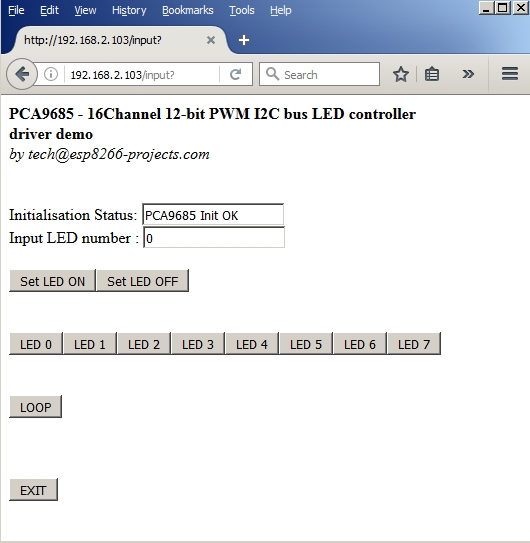
In the ESP Basic Web editor interface Type & Save your program as "PCA9685.bas" and Run it.
If all OK the result should look as below:

No comments:
Post a Comment